Heat exchange and condensation equipment series
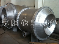
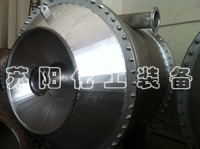
The spiral plate heat exchanger is a high-efficiency heat exchange equipment, suitable for heat transfer between vapor-vapor, vapor-liquid, and liquid-liquid. It is applicable to industries such as chemical, petroleum, solvent, pharmaceutical, food, light industry, textile, metallurgy, steel rolling, and coking. According to the structural form, it can be divided into non-detachable (Type I) spiral plate heat exchangers and detachable (Type II, Type III) spiral plate heat exchangers.
Years of practical use have proven that the spiral plate heat exchanger is indeed a high-efficiency heat exchange equipment. It is applicable to industries such as chemical, petroleum, solvent, pharmaceutical, food, light industry, textile, metallurgy, steel rolling, and coking. The heat exchanger absorbs contemporary international advanced technologies and is a liquid-liquid, vapor-water heat exchanger manufactured through unique optimized design. The product structure and process comply with the standards of the Swedish company Alfa Laval. The end face of the spiral plate adopts flanged argon arc welding, and the special process for the distance column is a capacitive energy storage contactor, which improves the internal and external quality and has been recognized by Baosteel, enabling it to replace imports.
The non-detachable spiral plate heat exchanger is designed according to the standards of the Ministry of Machinery JB/TQ724-89 for non-detachable spiral plate heat exchangers, including the regulations on the form, basic parameters, and dimensions. It has advantages such as simple manufacturing, low cost, small volume, and good heat transfer performance. However, it also has its disadvantages, such as the inability to perform mechanical cleaning and difficulty in maintenance when it breaks down. The user should select specific equipment according to the actual situation of the project to make it most effective.
Structure and Performance
1. This equipment is suitable for: liquid-liquid, gas-gas, and gas-liquid convective heat transfer. It can be used for steam condensation and liquid evaporation heat transfer. It can be selected by industrial departments such as chemical, petroleum, pharmaceutical, machinery, power, light industry, and textile.
2. This equipment is made by rolling two steel plates, forming two uniform spiral channels. The two heat transfer media can flow in full countercurrent, which is suitable for heat transfer with a small temperature difference, facilitating the recovery of low-temperature heat sources and enabling accurate control of the outlet temperature.
3. The nozzles on the shell have a tangential structure, with low local resistance. The curvature of the spiral channel is uniform, and the fluid does not undergo large changes in direction when flowing inside the equipment. The overall resistance is low, so the design flow velocity can be increased to achieve a higher heat transfer capacity.
4. The end face of the spiral channel is sealed by welding, with good sealing performance and a reliable structure.
5. It is difficult to maintain, especially when there is a problem with the internal plates. It is extremely difficult to repair. Some factories turn off all the welds at both ends of the equipment, flatten the plates, repair the welds, and then re-roll them. This consumes too much man-hours. Therefore, anti-corrosion is very important when selecting a spiral plate heat exchanger.
6. Mechanical cleaning cannot be performed. Production practice has proven that compared with ordinary tubular heat exchangers, the spiral plate heat exchanger is not easy to be blocked. In particular, suspended particle impurities such as sediment and small shells are not easy to deposit in the spiral channel. The reasons are as follows: First, because it is a single channel, once impurities deposit in the channel, the circulating flow velocity will increase to flush them out. Second, because there are no dead corners in the spiral channel, impurities are easy to be flushed out.
7. Because there are distance columns in the spiral channel to support the channel spacing, fibrous impurities (such as cotton yarn, straw sticks, leaves, etc.) must not enter the inside of the heat exchanger.
8. Strictly control the outlet temperature of the cooling water below the scaling temperature.
9. Commonly used cleaning methods are steam blowing or alkaline cleaning. Steam should be blown into the nozzles to blow out impurities from the equipment. Many user factories believe that this is an effective method.
Detachable (Type II, Type III) Spiral Plate Heat Exchangers
The structural principle is basically the same as that of the non-detachable heat exchanger, but the channels can be disassembled for cleaning, and both ends are sealed with heads. It is especially suitable for liquid-liquid exchange of viscous and precipitating liquids, as well as gas-liquid and steam condensation. Since the detachable heat exchanger needs to add components such as heads and flanges, the equipment cost is slightly higher than that of the non-detachable heat exchanger.
Basic Parameters
The nominal pressure PN of the spiral plate heat exchanger is specified as 0.6, 1, 1.6, 2.5 Mpa (i.e., the original 6, 10, 16, 25 kg/cm²) (referring to the maximum working pressure of a single channel). The test pressure is 1.25 times the working pressure.
The materials of the part of the spiral plate heat exchanger in contact with the medium are Q235A and Q235AF for carbon steel, and SUS321 and SUS304 for stainless acid-resistant steel. Other materials can be selected according to user requirements.
Permissible operating temperature: For carbon steel, t = 0 to +350°C; for stainless acid-resistant steel, t = -40 to 500°C. The temperature increase and pressure reduction range shall comply with the relevant regulations of pressure vessels. When selecting this equipment, appropriate process calculations should be carried out to make the fluid in the equipment channels reach a turbulent state. (Generally, the liquid flow velocity is 1 m/Sec and the gas flow velocity is 10 m/Sec).
If a single unit cannot meet the usage requirements, multiple units can be used in combination. However, the combination must comply with the following regulations:
Parallel combination, series combination: The equipment and channel spacing are the same. Mixed combination: One channel is in parallel, and one channel is in series.
Non-detachable (Type I) Spiral Plate Heat Exchangers made of Stainless Acid-Resistant Steel with PN 0.6, 1.6 MPa.
| Nominal Heat Exchange Area m² | Channel Spacing mm |
Calculated Heat Exchange Area m² |
Flow Rate When 1 m/sec Treatment Capacity m³/h |
Nominal Diameter of Nozzles | Model | Weight (kg) | |
| I 6B Type | I 16B Type | ||||||
| 1 | 6 | 1.0 | 3.89 | 40 | I 6,I 16B1-0.2/300-6 | 44 | 50 |
| 2 | 6 | 2.1 | 3.89 | 40 | I 6,I 16B2-0.2/400-6 | 78 | 85 |
| 4 | 6 | 4.4 | 8.2 | 50 | I 6,I 16B4-0.4/400-6 | 131 | 135 |
| 10 | 4.5 | 17.3 | 80 | I 6,I 16B4-0.5/450-10 | 129 | 133 | |
| 10 | 4.8 | 13.7 | 70 | I 6,I 16B4-0.4/500-10 | 161 | 205 | |
| 8 | 6 | 7.3 | 8.21 | 50 | I 6,I 16B8-0.4/500-6 | 212 | 215 |
| 10 | 7.85 | 17.3 | 80 | I 6,I 16B8-0.5/550-10 | 235 | 273 | |
| 10 | 7.3 | 20.90 | 80 | I 6,I 16B8-0.6/500-10 | 237 | 275 | |
| 10 | 6 | 11.1 | 8.21 | 50 | I 6,I 16B10-0.4/600-6 | 295 | 355 |
| 10 | 11.5 | 17.3 | 80 | I 6,I 16B10-0.5/650-10 | 315 | 405 | |
| 10 | 11.2 | 20.90 | 80 | I 6,I 16B10-0.6/600-10 | 305 | 395 | |
| 15 | 6 | 16.9 | 12.54 | 70 | I 6,I 16B15-0.6/600-6 | 415 | 490 |
| 10 | 14.72 | 17.3 | 80 | I 6,I 16B15-0.5/760-10 | 405 | 575 | |
| 10 | 15.0 | 28.1 | 80 | I 6,I 16B15-0.8/600-10 | 400 | 570 | |
| 14 | 15.6 | 39.3 | 100 | I 6,I 16B15-0.8/700-14 | 505 | 680 | |
| 20 | 6 | 21.7 | 8.21 | 50 | I 6,I 16B20-0.4/800-6 | 540 | 710 |
| 10 | 21.0 | 20.90 | 80 | I 6,I 16B20-0.6/800-10 | 555 | 735 | |
| 14 | 20.9 | 39.30 | 100 | I 6,I 16B20-0.8/800-14 | 660 | 830 | |
| 25 | 10 | 26.6 | 29.90 | 80 | I 6,I 16B25-0.6/900-10 | 610 | 950 |
| 14 | 26.9 | 39.20 | 100 | I 6,I 16B25-0.8/900-14 | 720 | 1060 | |
| 30 | 10 | 28.2 | 28.10 | 100 | I 6,I 16B30-0.8/800-14 | 750 | 1180 |
| 14 | 32.2 | 39.20 | 100 | I 6,I 16B30-0.8/1000-14 | 980 | 1370 | |
| 40 | 10 | 45.4 | 35.30 | 100 | I 6,I 16B40-1.0/900-10 | 1130 | 1515 |
| 14 | 40.2 | 19.4 | 125 | I 6,I 16B40-1.0/1000-14 | 1200 | 1630 | |
| 50 | 10 | 53.9 | 35.3 | 100 | I 6,I 16B50-1.0/1000-14 | 1360 | 1755 |
| 60 | 10 | 61.05 | 35.3 | 100 | I 6,I 16B60-1.0/1100-10 | 1920 | 2112 |
| 14 | 60.08 | 49.40 | 125 | I 6,I 16B60-1.0/1200-14 | 2000 | 2200 | |
| 80 | 10 | 81.83 | 35.3 | 100 | I 6,I 16B80-1.0/1200-10 | 2560 | 2816 |
| 14 | 80.9 | 49.40 | 125 | I 6,I 16B80-1.0/1400-14 | 2667 | 1934 | |
| 100 | 10 | 101.9 | 35.3 | 100 | I 6,I 16B100-1.0/1300-10 | 3200 | 3520 |
| 14 | 100.06 | 49.40 | 125 | I 6,I 16B100-1.0/1500-14 | 3333 | 3666 | |
| 120 | 10 | 115.5 | 35.3 | 100 | I 6,I 16B120-1.0/1500-10 | 3870 | 4257 |
| 14 | 119.0 | 49.40 | 125 | I 6,I 16B120-1.0/1700-14 | 4020 | 4422 | |
| 130 | 14 | 128.80 | 49.4 | 125 | I 6,I 16B130-1.0/1750-14 | 4241 | 4665 |
| 18 | 129.09 | 63.5 | 150 | I 6,I 16B130-1.0/1967-18 | 4462 | 4908 | |
| 150 | 14 | 148.1 | 49.4 | 125 | I 6,I 16B150-1.0/1890-14 | 4702 | 5172 |
| 18 | 148.2 | 63.5 | 150 | I 6,I 16B150-1.0/2010-18 | 4962 | 5458 | |


